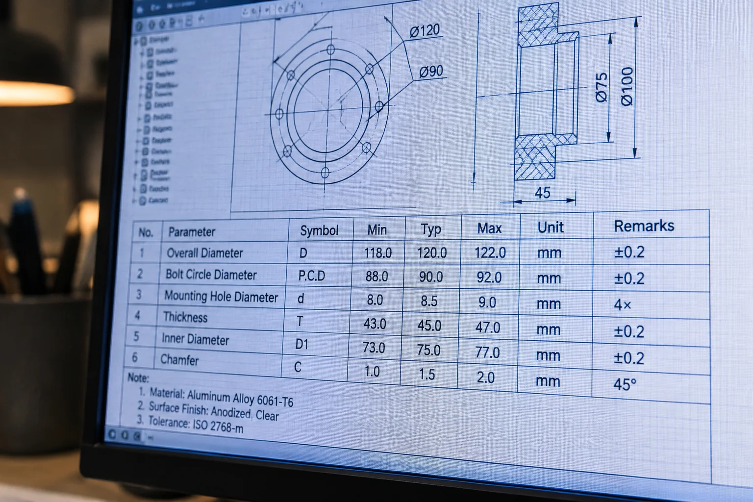
Spreadsheets embedded in CAD models often pass as simple parameter storage, yet every row and suppressed feature documents an engineering trade-off. When engineers view a design table through the lens of architectural intent, it turns into a transparent record of operational constraints, tooling boundaries, and product line maturity.
In mechanical engineering workflows, design tables are frequently generated to satisfy immediate sizing requests, such as adding a longer bracket variant or cutting an alternate bolt circle into an existing casting. Without proper structuring, these matrices rapidly devolve into cryptic columns of suppressed states and unlabelled dimensional overrides. Designers joining the project six months later find themselves guessing whether an unsuppressed boss exists because of structural rigidity requirements or simply because another team forgot to turn it off.
Treating the design table as an active architectural decision record transforms configuration management. Instead of treating rows as isolated geometry triggers, experienced teams structure their tables to highlight parent-child dependencies, standardized interfaces, and historical release milestones. A systematic design table communicates what changed, the physical limitation driving that divergence, and whether adjacent variants remain safe from downstream modifications.
Core Principles of Table-Driven Decision Records
- Primary Identification
- Alphanumeric keys tied directly to functional envelope
- Parameter Segmentation
- Fixed interface dimensions isolated from variant deltas
- State Documentation
- Explicit comments embedded alongside suppression toggles
- Integrity Verification
- Automated cross-checks against physical tooling limits
Decoding the Logic Behind Parameter Groupings
When opening an established design table, the arrangement of columns dictates how quickly an engineer can evaluate family coherence. Grouping mounting dimensions first establishes the common envelope that must never drift across variants. Secondary columns should contain the variable feature dimensions, while suppression states occupy the trailing block. This logical reading direction allows reviewers to immediately verify that foundational interfaces stay identical before inspecting localized geometric diversions.
A CAD configuration is never an arbitrary collection of dimensions. Every cell in a design table is a signed record of an engineering trade-off between manufacturing economy and functional capability.
Michael Brown, Senior CAD Systems Architect
Spotting Red Flags and Unintentional Variant Drift
A common failure mode in complex assemblies is silent divergence: an engineer updates an extrusion depth in the active workspace without realizing the change applies only to the current configuration, leaving the design table out of sync. Reading the table systematically during design gates surfaces anomalous values, such as solitary configurations missing fillet suppressions or displaying non-standard wall thicknesses. Establishing routine table audits ensures product variants remain interchangeable and manufacturing instructions correspond exactly to physical models.
Key Inspection Checkpoints for Engineering Reviews
- Verify that mounting interfaces and clearance boundaries remain completely identical across all standard configurations.
- Confirm every suppressed feature column correlates with a specific customer option or manufacturing tooling condition.
- Validate that configuration names convey physical envelopes or ratings rather than temporary project phase labels.
Need CAD Variant Architecture Assistance?
Discuss your complex parametric configuration setup directly with our engineering specialists.