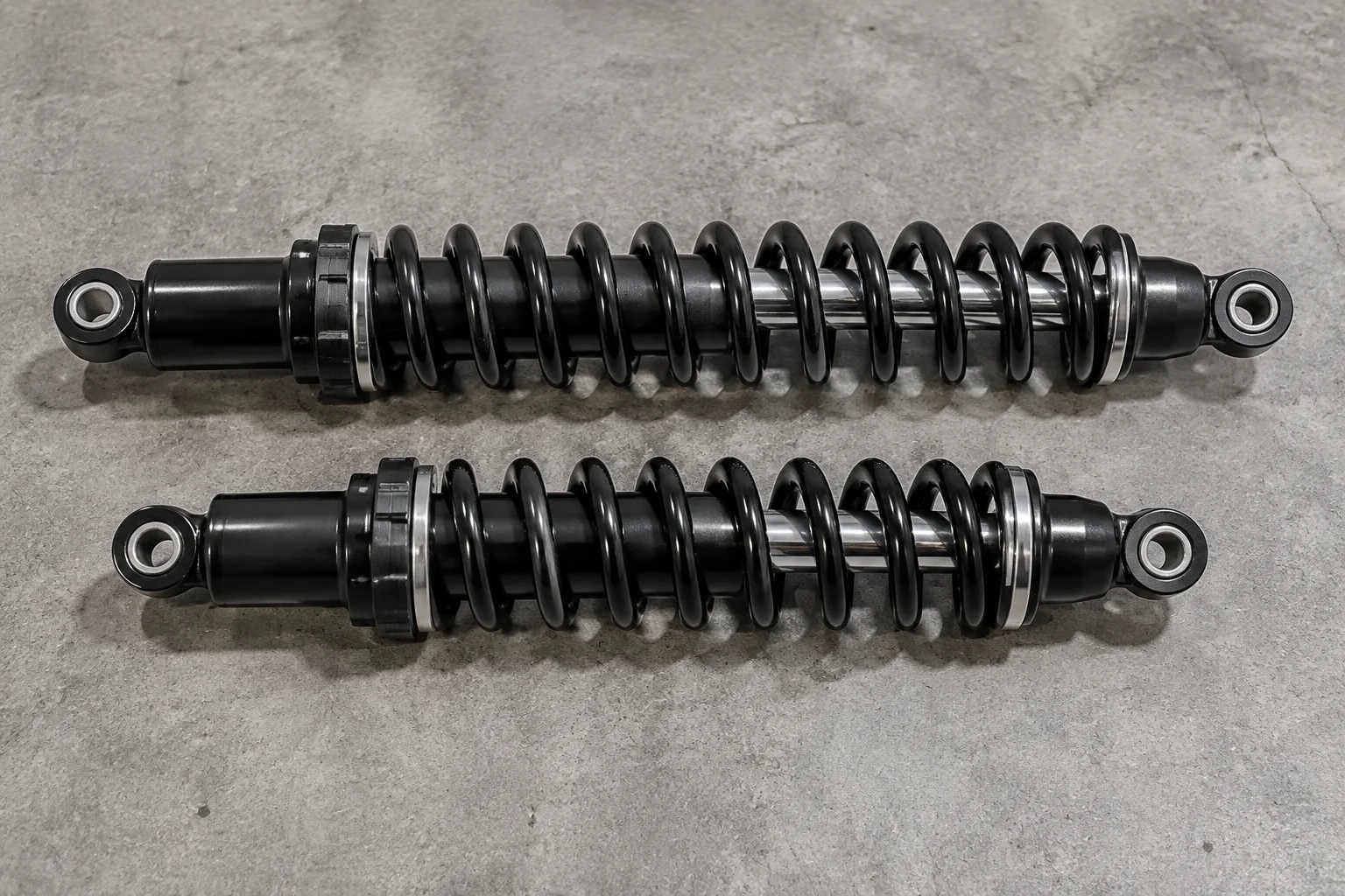
Stepping from a standard component to an extended variant rarely involves simply dragging a single length dimension across a CAD sketch.
In mechanical engineering and industrial tooling, extending a model creates immediate downstream impacts on mass distribution, wall stiffness, mounting moments, and internal components. When designers treat an extended model as merely a stretched version of standard geometry, severe integration errors emerge during manufacturing and assembly. The baseline configurations usually share primary cross-sections, but extended variants demand tailored feature sets to preserve performance under real-world operating conditions.
Managing these parametric transitions effectively requires establishing clear boundary rules inside design tables and CAD configuration trees. By distinguishing between shared foundational dimensions and tier-specific modifications, engineering teams preserve design intent, prevent cyclic rebuild errors, and ensure accurate bill of materials generation across the entire product lifecycle.
Primary Differences: Standard vs. Extended Tiers
- Working Stroke & Overall Length
- 180 mm baseline extended to 320 mm nominal stroke
- Guide Bushing & Internal Bearings
- Secondary tandem bushing activated for stroke guidance
- Mounting Flange Pattern
- 4-bolt standard upgraded to 6-bolt reinforced circle
- Wall Thickness & Reinforcement
- Tube wall increased from 4.0 mm to 5.5 mm to resist buckling
Secondary Geometric Shifts Caused by Extended Travel
When stroke length increases, mechanical components experience exponentially greater bending moments under transverse loading. In our industrial shock absorber family, extending the chamber length by 140 mm meant the standard single bronze bushing could no longer prevent rod deflection and seal extrusion. The extended configuration incorporates a dual-bushing arrangement and an auxiliary scraper ring. Furthermore, mounting brackets that function reliably on the standard model face elevated cyclic fatigue when mounted to the extended version, necessitating suppressed standard hole patterns in favor of reinforced multi-fastener patterns.
An extended configuration is an engineered mechanical revision, not a simple dimensional multiplier applied to an existing sketch.
Lisa Taylor, Lead Mechanical Architect
Best Practices for Modeling Tiered Variants in CAD
Maintain geometric stability by keeping origin datums and mating references identical across all model states. Suppress or unsuppress features deliberately rather than creating parallel unlinked sketches. When driving standard and extended models from an external design table or equations manager, document every dependent variable alongside its driving parameter. This ensures reviewers and junior engineers understand why a lengthened cylinder barrel also triggered an increased wall thickness and an extra pair of retaining clip grooves.
Key Configuration Takeaways
- Identify all secondary structural adaptations before modifying the primary driving length dimension.
- Use feature suppression matrices to handle internal hardware variations without severing parent sketch dependencies.
- Validate deflection limits and dynamic fatigue ratings independently for each model tier prior to release.
Need CAD Variant Architecture Assistance?
Discuss your complex parametric configuration setup directly with our engineering specialists.