The Role of Feature Suppression in Variant Architecture
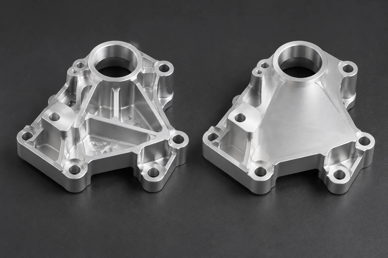
In modern parametric modeling, mechanical components frequently branch into specialized derivatives from a unified base part. A standard bracket might serve general mounting needs, while its industrial counterpart demands additional stiffening ribs, secondary cable pass-throughs, or supplementary counterbore arrays. Instead of branching into isolated files that drift out of sync, designers leverage feature suppression within multi-configuration models to toggle individual operations on and off.
However, suppressing geometry is far more consequential than simply toggling visibility. When a feature is suppressed, the CAD engine completely removes its analytical topology, faces, and vertex IDs from memory for that active state. If downstream sketches, auxiliary planes, or mates rely on an edge generated by that feature, the software loses its references, triggering model errors that cascade into engineering drawings and bill-of-materials exports.
Suppression modifies topology, not appearance. When you extinguish an edge, every constraint anchored to it becomes an orphan.
Parametric Truth: Mapping Feature States Across Family Tiers
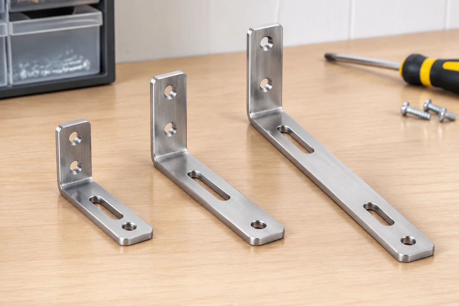
To maintain control over complex part families, engineers structure configurations around a tabular matrix. Rather than flipping toggle states randomly inside the feature tree, every active element is explicitly linked to the configuration table. This table governs geometry across the compact, standard, and extended versions of the component, making discrepancies visible before physical parts hit the machining floor.
| Parameter | Compact Variant | Standard Variant | Extended Variant |
|---|---|---|---|
| Nominal Length | 60 mm | 90 mm | 120 mm |
| Mounting Pattern | Pattern A (2x M4, Active) | Pattern A (2x M4, Active) | Pattern B (4x M5, Active; Pattern A Suppressed) |
| Auxiliary Slot | Suppressed | Suppressed | Active (12 mm x 30 mm Oblong) |
| Core Material | 6061-T6 Aluminum (Billet CNC Machined, Shared across all states) | ||
The matrix above highlights an imperative engineering rule: Pattern A remains active on both compact and standard parts, but the extended variant introduces Pattern B while suppressing Pattern A entirely. Because Pattern A is suppressed, downstream drawing callouts referencing its hole centers must point to configuration-specific annotation views, avoiding phantom dimensions on manufacturing shop prints.
Eliminating Downstream Reference Breaks and Broken Mates
Architecting a resilient multi-configuration CAD part requires disciplined sketch-to-parent mapping. When configuring items that switch features between unsuppressed and suppressed states, design teams apply three defensive modeling principles:
- Direct Sketch Attachment to Fundamental Datum Planes: Never sketch on the planar face of a feature that might be suppressed in alternative variants. Anchor sketches strictly to base reference planes or independent construction datums.
- Isolate Edge Fillets and Cosmetic Chamfers: Combine cosmetic edge treatments into feature groups that deactivate alongside their host boss or pocket, rather than blending fillets across shared and configured bodies.
- Decouple Assembly Mating Surfaces: When mating parts in sub-assemblies, constrain components to coordinate systems, primary axes, or global datums rather than transient faces that vanish under variant suppression.
Adhering to these structural boundaries ensures that switching configurations never triggers rebuild warnings or turns the tree into a web of yellow warnings and red error icons.
Verification Workflow for Production-Ready Releases
Before handing CAD files over to machining, casting, or tooling vendors, design review teams must execute an automated rebuild cycle through all active configurations. This step catches suppressed features that accidentally caused sketch geometry to dangle or drawing sheets to lose critical ordinate dimensions. An unverified configuration can sit dormant for months until a factory supervisor attempts to generate toolpaths for an extended model, discovering broken sketches only at setup time.
Establishing a rigid check ensures that mass properties, volume calculations, and center of gravity coordinates are logged for every variant state. In our documentation workflow, every suppression state must be accounted for with a corresponding design note, ensuring full traceability from digital CAD model to the physical assembly line.