Why Engineers Create Configurations
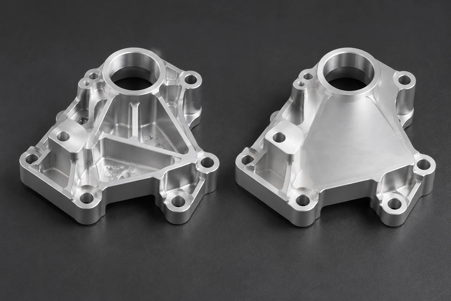
Engineering workflows demand adaptable models, yet creating a new CAD configuration should always stem from explicit physical intent. Designers often introduce new model states on a whim, branching out variations that differ only by a nominal chamfer or an experimental pocket. Without a documented purpose, configuration trees swell quickly into maintenance liabilities. When five configurations look nearly identical in the viewport, team members struggle to discern which version matches a specific bill of materials or customer requirement.
True configuration intent begins with identifying what must remain immutable versus what adapts to application constraints. Mounting footprints, bore diameters, or load-bearing webs often anchor an entire component line. If an engineer modifies an anchor feature without documenting why the modification exists in only one configuration, downstream assemblies inevitably misalign during production runs.
A configuration is an active engineering commitment. If a variant cannot justify its existence on a procurement drawing, it does not belong in the production model tree.
Parametric Logic and Common Baselines
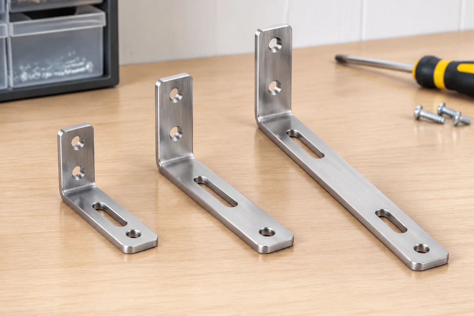
Parametric tables provide clarity by mapping functional attributes across variant instances. Instead of hunting through nested sketches, reviewers can inspect variable dimensions and suppressed states in a unified matrix. Consider an actuator bracket family designed to accommodate different torque ratings:
| Parameter | Compact Variant | Standard Variant | Extended Variant |
|---|---|---|---|
| Nominal Length | 85 mm | 120 mm | 165 mm |
| Mounting Pattern | 2x M6 In-Line | 4x M6 Rectangular | 4x M8 Heavy-Duty |
| Auxiliary Slot | Suppressed | Active (8x20 mm) | Active (10x30 mm) |
| Core Material | 6061-T6 Aluminum (Hard Anodized) | ||
By laying out these variables side-by-side, team members immediately grasp why three variants exist. Each variation answers a distinct operational envelope rather than an arbitrary aesthetic preference.
Controlling Feature States Without Parent Breaks
Suppressing features across configurations is powerful, but careless suppression can invalidate downstream sketch references and child fillets. Mechanical reliability demands disciplined hierarchy inside the feature tree:
- Base sketches must reference global datums and primary planes rather than temporary geometry that might be suppressed in alternative states.
- Auxiliary cuts, sensor taps, and decorative ribs should reside at the bottom of the feature tree so their toggling does not cascade into missing reference errors.
- Each suppressed entity must carry an explicit description or custom property indicating which configurations command its active state.
When downstream operations depend on faces that vanish in secondary configurations, models trigger rebuild warnings that waste hours during release reviews. Clean parent-child discipline resolves these headaches before drawings reach tooling engineers.
Validation Before Releasing a Configured Model
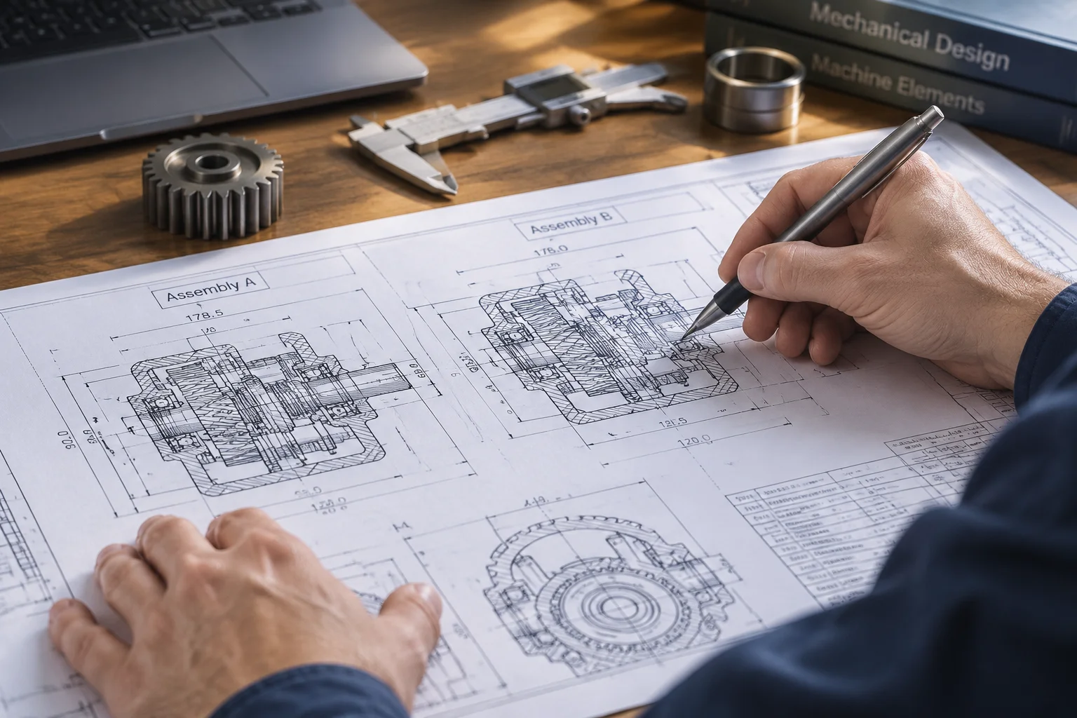
Before approving any variant case for production issuance, cross-check the configuration table against physical drawing sheets. Ensure that part numbers, finish descriptions, and mass properties evaluate cleanly across every active state. Discrepancies in total mass or center of gravity often signal an unsuppressed feature lurking where it was never intended.
Documenting configuration intent converts implicit CAD knowledge into explicit engineering intelligence. When manufacturing reviewers pick up a model six months later, well-structured configuration tables and sensible feature states tell a coherent story that prevents costly tooling modifications.