Engineering Scope and Family Definition
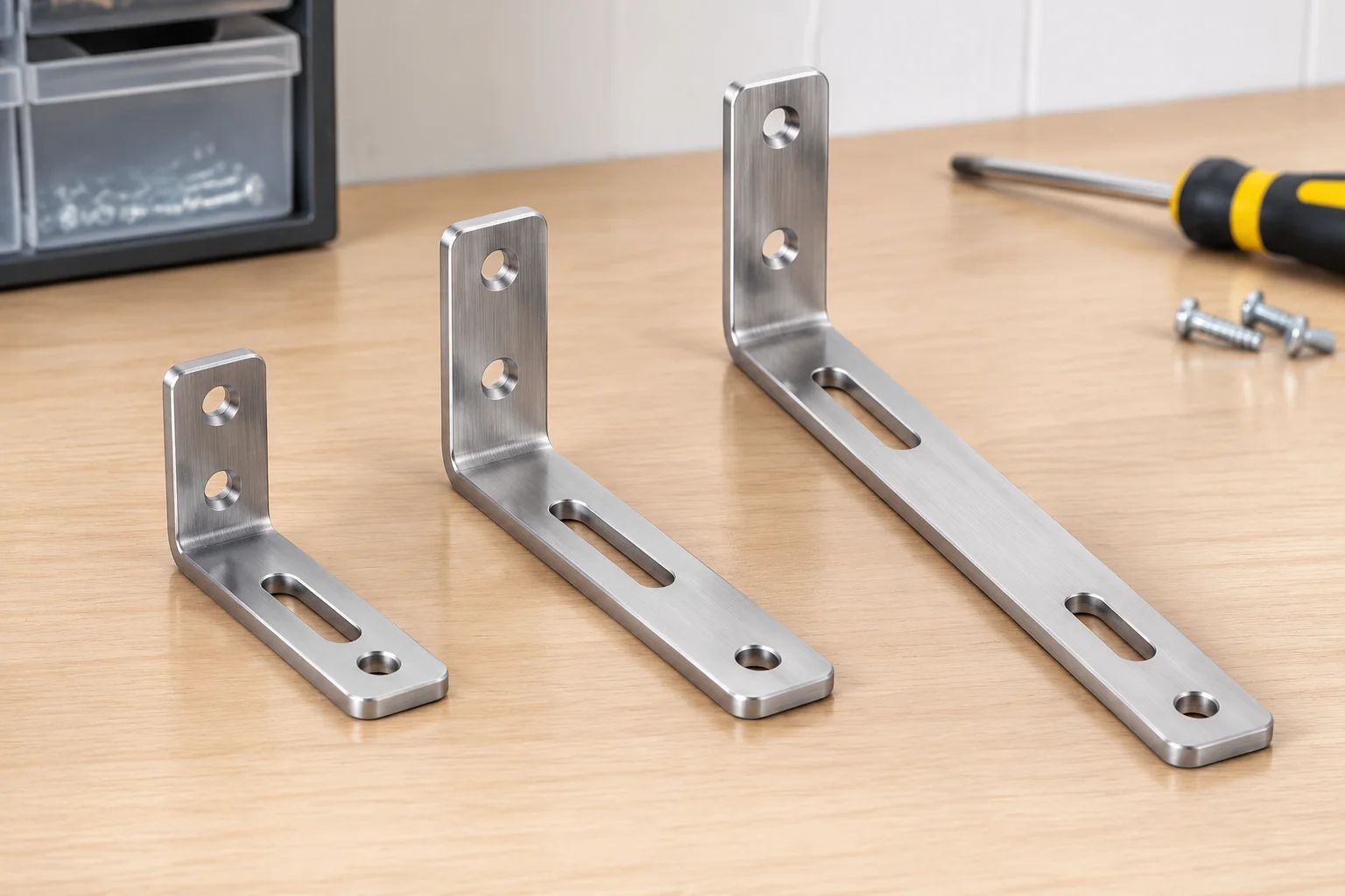
Hardware design teams frequently encounter brackets that perform identical basic functions across different machine enclosures but demand varying lengths to bridge structural gaps. In this industrial deployment, the design office chose to unify three distinct parts into a single parametric model tree rather than maintaining separate CAD files that drift out of alignment over time.
The three members—Compact, Standard, and Extended—serve automation cabinets ranging from shallow sensor enclosures to deep junction cabinets. Because all three versions share press-brake bending tools, maintaining identical flange depths and inner radii was non-negotiable. Storing the geometry in one configuration table ensured that any tooling revision automatically updated every variant simultaneously.
A parametric model family is a functional contract between engineering and fabrication: variables may shift systematically, but shared manufacturing tooling parameters must remain absolute.
Parametric Table Matrix and Shared Constants
The core configuration logic operates through an integrated design table driving dimensional values directly from spreadsheet cells into model sketches. The following table highlights the exact mechanical parameters governing each variant in the release package:
| Parameter | Compact Variant | Standard Variant | Extended Variant |
|---|---|---|---|
| Nominal Length | 60 mm | 90 mm | 120 mm |
| Mounting Pattern | Pattern A (2x M5 Holes @ 40 mm) | Pattern A (2x M5 Holes @ 40 mm) | Pattern B (3x M5 Holes @ 35 mm Pitch) |
| Auxiliary Slot | Suppressed (None) | Suppressed (None) | Unsuppressed (12 x 30 mm Oblong) |
| Core Material | 5052-H32 Aluminum Alloy (3.0 mm Sheet Thickness) | ||
All values in this table are illustrative educational examples, not engineering-verified product dimensions.
Fixing material gauge and alloy specification across all iterations allowed the laser-cutting cell to nest all three bracket variants onto common sheet blanks during mixed-model production runs, reducing scrap by sixteen percent.
Suppression Hierarchy and Topology Stability
Feature suppression is often vulnerable to broken assembly mates when configurations switch. To preserve topological stability across the assembly lifecycle, the CAD model architecture follows strict hierarchical dependency rules:
- Auxiliary pass-through slots are constrained solely to the main web centerplane, ensuring their suppression in Compact and Standard states cannot trigger dangling reference warnings.
- Hole Pattern B derives from a dedicated layout sketch that is deactivated on shorter variants without affecting the coordinate origins used by downstream assembly constraints.
- Edge break chamfers around auxiliary slots reside directly beneath the parent cutout in the feature manager tree, preventing orphan cosmetic features during table regeneration.
Adhering to this structured suppression sequence guarantees that design reviewers can toggle between family members in complex machine assemblies without facing rebuild warnings or detached coordinate systems.
Drawing Verification and Production Release Rules
Before pushing the bracket family to the release vault, the engineering review team checks flat pattern bend deductions against current shop-floor brake press V-die tooling. While the nominal profile extends from 60 mm to 120 mm, the K-factor remains uniformly locked at 0.44 to match the standard shop tooling envelope.
The single production drawing utilizes a master parameter matrix rather than duplicated views. Each configuration row clearly denotes the part suffix, overall cut length, active hole count, and total stamped mass, empowering manufacturing operators to inspect any of the three brackets from a single verified document.