Architectural Foundations of Parametric Tables
Mechanical product families frequently rely on parametric tables to govern dozens of interrelated dimensional states. Rather than rebuilding individual CAD models for each catalog entry, design tables centralize dimensions, equations, and active feature flags in a single spreadsheet-driven schema. When configured thoughtfully, a parametric matrix bridges the gap between mechanical engineering intent and automated geometric derivation.
The true vulnerability in tabular configuration management occurs when parameter rows proliferate without strict naming hierarchy. When a designer edits an unconstrained cell, downstream features risk silent failures or detached mate references. Building resilient parametric tables requires dividing variables into fundamental geometric drivers, derived equations, and distinct suppression controls.
A parametric table is not merely a dimensional lookup list; it is an executable engineering specification that controls physical topology across every variant state.
Dimensional Parameter Mapping and Matrix Structure
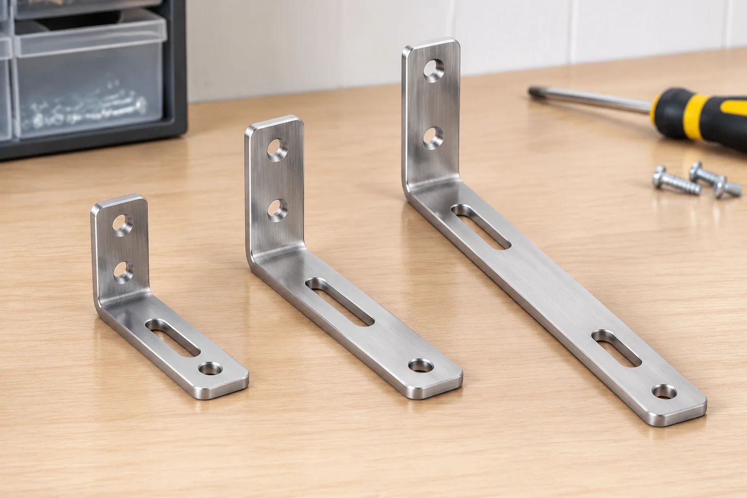
In standard part families such as structural mounting brackets or modular housings, core dimensions vary across discrete increments while fundamental functional interfaces remain constant. The table below demonstrates the parameter mapping logic for a typical bracket configuration family, illustrating how geometric dimensions and auxiliary slots interact across sizing tiers:
| Parameter | Compact Variant | Standard Variant | Extended Variant |
|---|---|---|---|
| Nominal Length | 60 mm | 90 mm | 120 mm |
| Mounting Pattern | Pattern A (Dual M6) | Pattern A (Dual M6) | Pattern B (Quad M6) |
| Auxiliary Slot | Suppressed (No) | Suppressed (No) | Unsuppressed (Yes) |
| Core Material | 6061-T6 Aluminum (Shared Specification) | ||
By keeping the base alloy and primary wall thicknesses standardized while parameterizing length and mounting hole distributions, the design table isolates variance to controlled cells. Downstream manufacturing processes can easily reference this matrix without interpreting conflicting drawing notes.
Governing Feature Suppression and Structural States
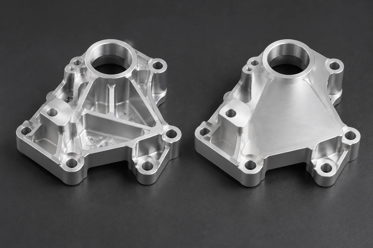
Feature suppression represents one of the most powerful mechanisms in parametric CAD tables, yet it introduces acute risk if parent-child references are neglected. When an auxiliary slot, gusset, or counterbore is suppressed in a specific variant, downstream sketches dependent on its geometry can break instantly.
- Anchor sketches solely to invariant datum planes or base geometry rather than faces belonging to suppressible features.
- Explicitly declare suppression states in design table headers using precise software-compatible tokens ($STATE@FeatureName).
- Group dependent secondary operations (such as edge fillets and chamfers) into modular feature folders that toggle as a unified block.
Adhering to these suppression rules ensures that activating the Compact or Standard configuration does not create orphaned dimensions or geometry reconstruction errors during assembly updates.
Validation Checklist and Design Table Best Practices
Before checking a parametric model back into product data management (PDM) repositories, teams should perform an automated configuration cycle. Switch sequentially through every listed variant in the table, verify that mass properties update within expected tolerances, and check that drawing views update their associative bill of materials correctly.
Furthermore, freeze table-driven sketch equations once a revision level is released. Unintended formula changes in shared spreadsheets can quietly ripple through legacy assemblies, corrupting drawing references across entire product catalogs.