Establishing Configuration Baseline & Verification Scope
When multi-configuration CAD models evolve over extended release cycles, engineers frequently assume downstream variants inherit baseline adjustments automatically and cleanly. Yet subtle changes in sketch fillets, datum plane orientations, or feature order can propagate through child configurations in unexpected ways. Checking multiple product versions requires stepping away from intuitive modeling habits and treating each configured state as an independent mechanical artifact requiring formal validation.
A reliable validation cycle begins with cataloging every active version defined inside the parametric family. Rather than inspecting variants ad hoc, quality teams set up a baseline verification scope that maps exact functional boundaries: geometric clearances, suppressed mounting tabs, alternate hole taps, and unique surface treatments. Without a clear boundary scope, downstream drawing sheets easily display outdated configurations or silently suppress critical manufacturing features.
A configuration is a design decision, not just an alternate display state. If it ships under a unique part number, it demands an explicit verification record.
Side-by-Side Parametric Inspection Matrix
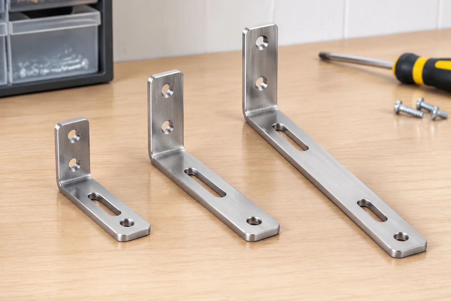
Cross-variant consistency is best audited using an explicit parameter matrix. By isolating the independent driving parameters against dependent calculated dimensions, reviewers quickly detect values that have drifted or failed to update during global equation adjustments.
| Parameter | Compact Variant | Standard Variant | Extended Variant |
|---|---|---|---|
| Nominal Length | 60 mm (±0.2) | 90 mm (±0.2) | 120 mm (±0.2) |
| Mounting Pattern | Pattern A (Dual M6) | Pattern A (Dual M6) | Pattern B (Quad M8) |
| Auxiliary Slot | Suppressed | Suppressed | Active (12x40 mm) |
| Core Material | 6061-T6 Aluminum (Hard Anodized, Clear) | ||
Reviewing the matrix highlights intentional divergence—such as the transition from dual M6 bores to quad M8 fasteners on extended variants—while verifying that common attributes like core material specifications and base wall thicknesses remain harmonized across the entire family tree.
Managing Active vs. Suppressed State Integrity
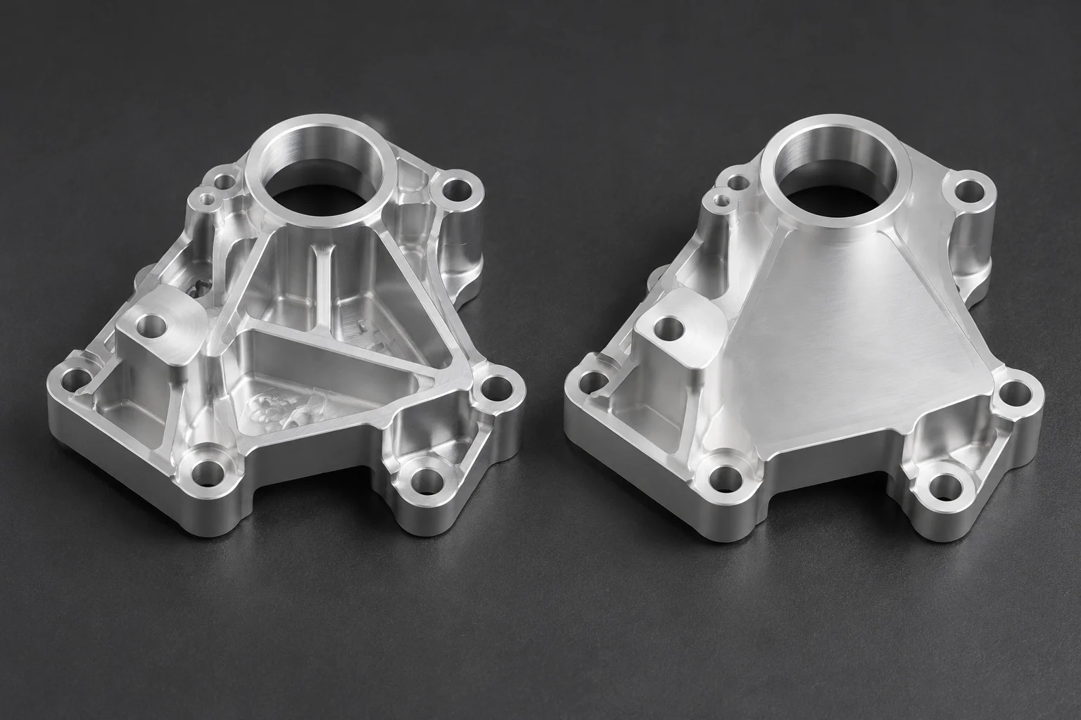
Suppressed features represent one of the most common points of failure when maintaining multi-variant part families. A suppression state intended only for a lightweight or compact model can accidentally cascade into siblings through shared sketch references or parent-child dependencies.
- Validate sketch reference planes to ensure suppressed parent bosses do not collapse dependent child sketches in sibling configurations.
- Inspect secondary machining operations and fillets that rely on edges that only exist in specific higher-tier versions.
- Audit custom metadata fields, ERP material codes, and drawing title-block parameters across all active table rows before file lock.
When feature suppression is strictly isolated to terminal leaf nodes of the model tree, parent geometry stays robust, preventing unpredictable rebuild errors when switching configurations inside top-level manufacturing assemblies.
Pre-Release Verification Protocol & QA Sign-Off
Before approving a multi-version CAD model for tooling release or purchasing handoff, engineering teams should execute an end-to-end automated rebuild test. Stepping through every configured state with forced rebuild flags enabled flushes out hidden topology warnings that typical interactive navigation skips.
In addition, checking mass properties against expected calculated thresholds prevents mislabeled variants from reaching production. An unexpected jump or drop in component mass immediately signals an unsuppressed pocket, a missing rib, or an erroneous wall thickness dimension that slipped past visual inspection.