The Cost of Unanswered Configuration Assumptions
Releasing an engineering model containing several configurations requires much more scrutiny than approving a single standalone component. Multiple CAD variants often appear interchangeable on the modeling canvas while hiding serious functional divergence in fastener patterns, weight limits, and internal tolerances. Manufacturing floors inevitably suffer scrapped raw stock when an unverified dimensional shift escapes design review undetected.
Product engineers frequently ask whether a variant represents an internal fabrication variation or an entirely separate SKU intended for field interchangeability. Incomplete answers to this baseline inquiry lead to corrupted bills of materials and costly assembly line stoppages during first-article fabrication.
A variant release is an institutional contract that every parameter change preserves the functional integrity of surrounding assemblies.
The Variant Matrix Comparison
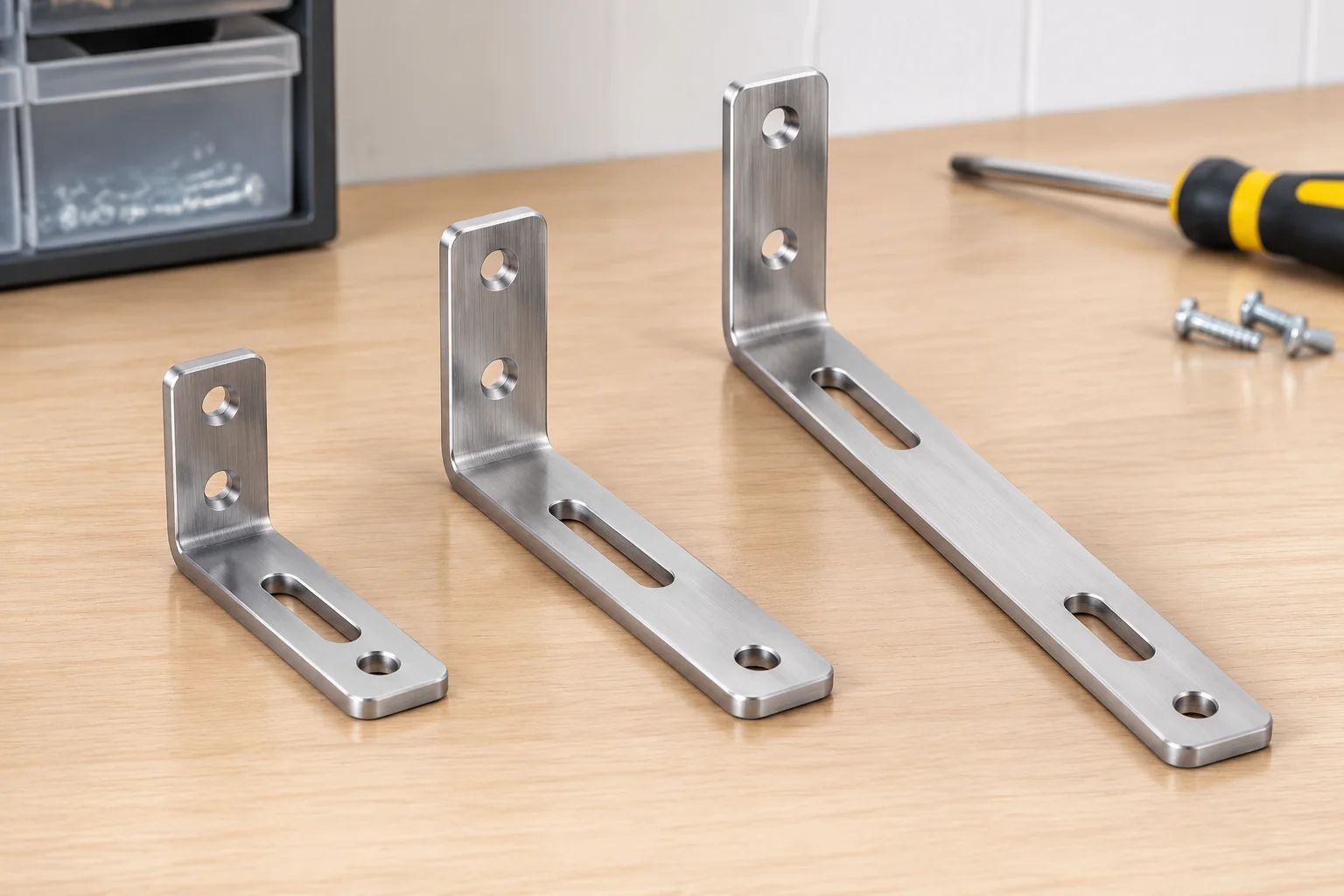
Every formal pre-release check begins by establishing a comprehensive property grid that exposes dimensional deltas alongside active suppression flags across all configurations. The bracket review sample below illustrates how three related configurations diverge in length, fastener spacing, and tooling geometry while preserving an identical baseline material stock.
| Parameter | Compact Variant | Standard Variant | Extended Variant |
|---|---|---|---|
| Nominal Length | 60 mm | 90 mm | 120 mm |
| Mounting Pattern | Dual M6 (Pattern A) | Dual M6 (Pattern A) | Quad M8 (Pattern B) |
| Auxiliary Slot | Suppressed | Suppressed | Active (12 × 35 mm) |
| Core Material | 6061-T6 Extruded Aluminum (Anodized Clear) | ||
The table proves why clear variant names matter. The extended variant does not simply stretch length; it also switches to heavier fasteners and activates a dedicated routing slot that demands different machining clearances.
Suppression Discipline & Structural Checks
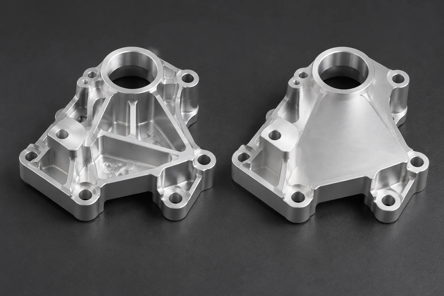
Feature suppression forms the backbone of multi-configuration modeling, yet it introduces subtle failure modes when parent-child dependencies are overlooked. Experienced design reviewers inspect the model tree systematically under each active configuration before granting final release approvals.
- Verify that suppressed cuts or holes do not orphan subsequent fillets, chamfers, or cosmetic threads in related branch states.
- Examine top-level assemblies to ensure that standard mates remain anchored to unsuppressed datum geometry rather than transient variant edges.
- Audit configuration-specific drawing sheets to confirm that suppressed elements do not leave dangling dimension witness lines or empty detail views.
Resolving these geometric dependencies early safeguards downstream operations from costly rebuild errors when other team members open the model later.
Final Pre-Release Questionnaire
Design squads must run through a structured set of questions before changing model status from Development to Released. Has the thermal expansion profile changed across variations? Does the manufacturing tooling require separate clamping fixtures for the longest variant? Are part numbers assigned uniquely in the configuration properties dialog so that purchasing systems register three distinct items rather than overwriting a single stock code?
Documenting clear answers directly into the design table creates an audit trail that preserves engineering intent across future revisions and saves hours during tooling setup.